Home › Unlabelled ›
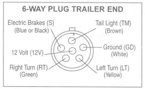
Wiring Diagram For Trailer With Electric Brakes : Breakaway Kit Installation For Single And Dual Brake Axle Trailers Etrailer Com / 7 way plug wiring diagram standard wiring* post purpose wire color tm park light green (+) battery feed black rt right turn/brake light brown lt left turn/brake light red s trailer electric brakes blue gd ground white a accessory yellow this is the most common (standard) wiring scheme for rv plugs and the one used by major auto manufacturers today.
Wiring Diagram For Trailer With Electric Brakes : Breakaway Kit Installation For Single And Dual Brake Axle Trailers Etrailer Com / 7 way plug wiring diagram standard wiring* post purpose wire color tm park light green (+) battery feed black rt right turn/brake light brown lt left turn/brake light red s trailer electric brakes blue gd ground white a accessory yellow this is the most common (standard) wiring scheme for rv plugs and the one used by major auto manufacturers today.. Each component should be set and connected with different parts in specific way. Variety of trailer breakaway wiring schematic. Electric trailer brake wiring and parts diagrams click here to shop for electric trailer brakes and brake parts the two main types of electric brake assemblies for axles 7k and below are forward self adjusting (fsa) and manual adjusting. When comparing wire thickness, a smaller gauge number represents a thicker wire. These directions will likely be easy to grasp and apply.
With this kind of an illustrative manual, you are going to be capable of troubleshoot, stop, and total your assignments with ease. The trailer brakes are activated electronically by the use of a brake control box mounted under the dash in the tow vehicle. Each component ought to be set and connected with different parts in particular manner. We then run a jumper wire from the electric brake power wire to the right side brake assemblies (see photo). When comparing wire thickness, a smaller gauge number represents a thicker wire.
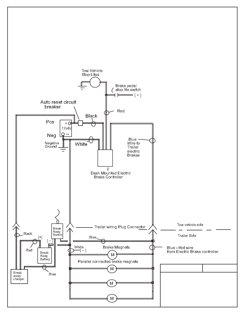
Diagram Brake Force Trailer Brake Controller Wiring Diagram Full Version Hd Quality Wiring Diagram Diagramhs Casavacanzeaurelia It from tonetastic.info This short video is about trailer brakes, electric brakes and wiring. When comparing wire thickness, a smaller gauge number represents a thicker wire. A brake controller wiring installation kit makes light work! There is additional wiring involved in tying your braking system and. The following diagram is a general guide for wiring common brake controllers into cars. We then run a jumper wire from the electric brake power wire to the right side brake assemblies (see photo). A wiring diagram is a streamlined conventional pictorial representation of an electric circuit. Even with a standard minimum of 16 gauge cables used in some trailer circuits, elecbrakes functions correctly.
The following diagram is a general guide for wiring common brake controllers into cars.
It also talks about electric brake controller.thanks for watching ! 7 way plug wiring diagram standard wiring* post purpose wire color tm park light green (+) battery feed black rt right turn/brake light brown lt left turn/brake light red s trailer electric brakes blue gd ground white a accessory yellow this is the most common (standard) wiring scheme for rv plugs and the one used by major auto manufacturers today. We then run a jumper wire from the electric brake power wire to the right side brake assemblies (see photo). Trailer wiring diagrams trailer wiring connectors various connectors are available from four to seven pins that allow for the transfer of power for the lighting as well as auxiliary functions such as an electric trailer brake controller, backup lights, or a 12v power supply for a winch or interior trailer lights. With this kind of an illustrative manual, you are going to be capable of troubleshoot, stop, and total your assignments with ease. A wiring diagram is a simplified conventional photographic depiction of an electric circuit. Of transportation requires that trailers equipped with brakes have a trailer break away system for activation of the trailer brakes, in the event that the trailer should become detached from the tow vehicle during highway travel. Assortment of electric trailer brake wiring schematic. They also provide a wire for a ground connection. It reveals the elements of the circuit as streamlined forms, and also the power and signal connections between the gadgets. Wiring diagram for common plugs breakaway switches. Trailer wiring diagrams trailer wiring connectors. The trailer brakes are activated electronically by the use of a brake control box mounted under the dash in the tow vehicle.
We then run a jumper wire from the electric brake power wire to the right side brake assemblies (see photo). Trailer wiring diagrams trailer wiring connectors. This wiring electric trailer brakes diagram model is more acceptable for sophisticated trailers and rvs. It also talks about electric brake controller.thanks for watching ! Elecbrakes must be connected to trailer wiring circuits as outlined in the wiring diagram.
Trailer Wiring Diagrams Johnson Trailer Co from johnsontrailerco.com Wiring diagram for common plugs breakaway switches. If not, the arrangement will not function as it ought to be. The other type of brake system is electronically controlled electric brake control wiring. Of transportation requires that trailers equipped with brakes have a trailer break away system for activation of the trailer brakes, in the event that the trailer should become detached from the tow vehicle during highway travel. A wiring diagram is a streamlined traditional pictorial representation of an electrical circuit. Electric brake controllers provide power to the magnets to actuate the trailer brakes. It shows the components of the circuit as streamlined shapes, and the power and also signal connections in between the devices. Each component should be set and connected with different parts in specific way.
A brake controller wiring installation kit makes light work!
What gauge wire for electric trailer brakes? There is additional wiring involved in tying your braking system and. They also provide a wire for a ground connection. The following diagram is a general guide for wiring common brake controllers into cars. This automobile is designed not only to travel one location to another but also to take heavy loads. Elecbrakes must be connected to trailer wiring circuits as outlined in the wiring diagram. A wiring diagram is a simplified conventional photographic depiction of an electric circuit. The other type of brake system is electronically controlled electric brake control wiring. It shows the components of the circuit as streamlined shapes, and the power and also signal connections in between the devices. If not, the arrangement will not function as it ought to be. Each component ought to be set and connected with different parts in particular manner. You can also find other images like wiring diagram, parts diagram, replacement parts, electrical diagram, repair manuals, engine diagram, engine scheme, wiring harness, fuse box, vacuum diagram, timing belt, timing. With this kind of an illustrative manual, you are going to be capable of troubleshoot, stop, and total your assignments with ease.
Trailer wiring diagrams trailer wiring connectors. These directions will likely be easy to grasp and apply. The trailer brakes are activated electronically by the use of a brake control box mounted under the dash in the tow vehicle. The following diagram is a general guide for wiring common brake controllers into cars. Each component ought to be set and connected with different parts in particular manner.
Electric Brake Control Wiring from www.championtrailers.com Trailer wiring diagrams trailer wiring connectors various connectors are available from four to seven pins that allow for the transfer of power for the lighting as well as auxiliary functions such as an electric trailer brake controller, backup lights, or a 12v power supply for a winch or interior trailer lights. Ensure it is sealed off and cannot create a short circuit with any other wire or the chassis. Generic electric brake wiring diagram for dash mounted brake controller & trailer mounted tap brakemaster electric breakaway kit. The other type of brake system is electronically controlled electric brake control wiring. Of transportation requires that trailers equipped with brakes have a trailer break away system for activation of the trailer brakes, in the event that the trailer should become detached from the tow vehicle during highway travel. As the name implies, they use four wires to carry out the vital lighting functions. Even with a standard minimum of 16 gauge cables used in some trailer circuits, elecbrakes functions correctly. Variety of trailer breakaway wiring schematic.
Assortment of electric trailer brake wiring schematic.
As the name implies, they use four wires to carry out the vital lighting functions. This automobile is designed not only to travel one location to another but also to take heavy loads. It reveals the parts of the circuit as streamlined forms, as well as the power and signal connections in between the gadgets. Controller called the predator dx2 ®. Generic electric brake wiring diagram for dash mounted brake controller & trailer mounted tap brakemaster electric breakaway kit. If you are lucky (and have the factory tow package already installed) you may already have this wire running from under the dash to the rear of the vehicle. A wiring diagram is a streamlined traditional pictorial representation of an electrical circuit. Elecbrakes must be connected to trailer wiring circuits as outlined in the wiring diagram. Each component ought to be set and connected with different parts in particular manner. Trailer wiring diagrams trailer wiring connectors. How electric trailer brakes work. It also talks about electric brake controller.thanks for watching ! Each component should be set and connected with different parts in specific way.