Home › Unlabelled ›
Trailer Wiring Diagram With Electric Brakes : Trailer Wiring Diagrams Etrailer Com : There is a range of wire sizes available for trailer circuits and electric brake wiring.
Trailer Wiring Diagram With Electric Brakes : Trailer Wiring Diagrams Etrailer Com : There is a range of wire sizes available for trailer circuits and electric brake wiring.. The trailer wiring diagram shows this wire going to all the lights and brakes. When you employ your finger or even stick to the circuit along with your eyes, it is easy to mistrace the circuit. They also provide a wire for a ground connection. White pin to your floor. With this kind of an illustrative manual, you are going to be capable of troubleshoot, stop, and total your assignments with ease.
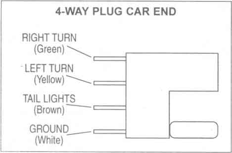
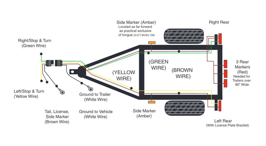
Splice down line from the switch; The four wires control the turn signals, brake lights and taillights or running lights. Wiring diagram comes with a number of easy to adhere to wiring diagram instructions. To make wiring a brake controlle A brake controller wiring installation kit makes light work!
Trailer Wiring Diagrams Johnson Trailer Co from johnsontrailerco.com 7 pin ebs trailer wiring diagram. White pin to your floor. Some trailer builders just connect this wire to the frame, then connect the ground from all the other lights and accessories to the frame as well. Trailer wiring diagrams trailer wiring connectors. A wiring diagram is a streamlined conventional pictorial representation of an electric circuit. It reveals the parts of the circuit as streamlined forms, as well as the power and signal connections in between the gadgets. What gauge wire for electric trailer brakes? How electric trailer brakes work.
It really is supposed to assist all of the typical person in developing a correct program.
This makes the process of assembling circuit easier. Ensure it is sealed off and cannot create a short circuit with any other wire or the chassis. If your vehicle is not equipped with a working trailer wiring harness, there are a number of different solutions to provide the perfect fit for your specific vehicle. The following diagram is a general guide for wiring common brake controllers into cars. 7 pin ebs trailer wiring diagram. Electric trailer brake wiring and parts diagrams click here to shop for electric trailer brakes and brake parts the two main types of electric brake assemblies for axles 7k and below are forward self adjusting (fsa) and manual adjusting. Do not disturb the position of the switch. Trailer wiring diagrams trailer wiring connectors. The four wires control the turn signals, brake lights and taillights or running lights. Elecbrakes must be connected to trailer wiring circuits as outlined in the wiring diagram. As the name implies, they use four wires to carry out the vital lighting functions. The red (stoplight) wire must be connected to the cold side of the brake pedal stoplight switch. Some trailer builders just connect this wire to the frame, then connect the ground from all the other lights and accessories to the frame as well.
It shows the components of the circuit as streamlined shapes, and the power and also signal connections in between the devices. When comparing wire thickness, a smaller gauge number represents a thicker wire. This wiring electric trailer brakes diagram model is more acceptable for sophisticated trailers and rvs. Various connectors are available from four to seven pins that allow for the transfer of power for the lighting as well as auxiliary functions such as an electric trailer brake controller, backup lights, or a 12v power supply for a winch or interior trailer lights. Trailer wiring diagrams trailer wiring connectors various connectors are available from four to seven pins that allow for the transfer of power for the lighting as well as auxiliary functions such as an electric trailer brake controller, backup lights, or a 12v power supply for a winch or interior trailer lights.
Trailer Wiring Diagram Wiring Diagrams For Trailers from www.truckspring.com 7 pin ebs trailer wiring diagram. A wiring diagram is a streamlined traditional pictorial representation of an electrical circuit. The trailer brakes are activated electronically by the use of a brake control box mounted under the dash in the tow vehicle. The service brake circuit must be disconnected from an existing trailer plug. This makes the process of assembling circuit easier. When you employ your finger or even stick to the circuit along with your eyes, it is easy to mistrace the circuit. This wiring electric trailer brakes diagram model is more acceptable for sophisticated trailers and rvs. It shows the components of the circuit as streamlined shapes, and the power and also signal connections in between the devices.
This makes the process of assembling circuit easier.
When you employ your finger or even stick to the circuit along with your eyes, it is easy to mistrace the circuit. The first element is symbol that indicate electrical component from the circuit. The following diagram is a general guide for wiring common brake controllers into cars. How electric trailer brakes work. The blue (brake output) wire must be connected to the trailer connector's brake wire. Trailer wiring diagrams trailer wiring connectors various connectors are available from four to seven pins that allow for the transfer of power for the lighting as well as auxiliary functions such as an electric trailer brake controller, backup lights, or a 12v power supply for a winch or interior trailer lights. A wiring diagram is a streamlined conventional pictorial representation of an electric circuit. They also provide a wire for a ground connection. The trailer wiring diagram shows this wire going to all the lights and brakes. However, the diagram is a simplified variant of this arrangement. Trailer wiring diagrams trailer wiring connectors. There is additional wiring involved in tying your braking system and. 7 pin ebs trailer wiring diagram.
The four wires control the turn signals, brake lights and taillights or running lights. The trailer brakes are activated electronically by the use of a brake control box mounted under the dash in the tow vehicle. The service brake circuit must be disconnected from an existing trailer plug. 7 pin ebs trailer wiring diagram. Do not disturb the position of the switch.
How To Wire Up Electric Trailer Brakes from cpi.studiod.com When you employ your finger or even stick to the circuit along with your eyes, it is easy to mistrace the circuit. The trailer wiring diagram shows this wire going to all the lights and brakes. The four wires control the turn signals, brake lights and taillights or running lights. Trailer electric brake wiring diagram from www.hhrvresource.com print the electrical wiring diagram off plus use highlighters to be able to trace the circuit. Do not disturb the position of the switch. Various connectors are available from four to seven pins that allow for the transfer of power for the lighting as well as auxiliary functions such as an electric trailer brake controller, backup lights, or a 12v power supply for a winch or interior trailer lights. This wiring electric trailer brakes diagram model is more acceptable for sophisticated trailers and rvs. The trailer brakes are activated electronically by the use of a brake control box mounted under the dash in the tow vehicle.
Various connectors are available from four to seven pins that allow for the transfer of power for the lighting as well as auxiliary functions such as an electric trailer brake controller, backup lights, or a 12v power supply for a winch or interior trailer lights.
Trailer electric brake wiring diagram from www.hhrvresource.com print the electrical wiring diagram off plus use highlighters to be able to trace the circuit. A wiring diagram is a streamlined conventional pictorial representation of an electric circuit. These directions will likely be easy to grasp and apply. Some trailer builders just connect this wire to the frame, then connect the ground from all the other lights and accessories to the frame as well. This wiring electric trailer brakes diagram model is more acceptable for sophisticated trailers and rvs. We then run a jumper wire from the electric brake power wire to the right side brake assemblies (see photo). Elecbrakes must be connected to trailer wiring circuits as outlined in the wiring diagram. Electric trailer brake wiring and parts diagrams click here to shop for electric trailer brakes and brake parts the two main types of electric brake assemblies for axles 7k and below are forward self adjusting (fsa) and manual adjusting. Assortment of electric trailer brake wiring schematic. The other type of brake system is electronically controlled electric brake control wiring. When you employ your finger or even stick to the circuit along with your eyes, it is easy to mistrace the circuit. Collection of wiring diagram for utility trailer with electric brakes. 7 pin ebs trailer wiring diagram.